
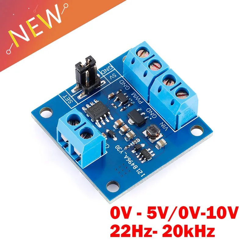
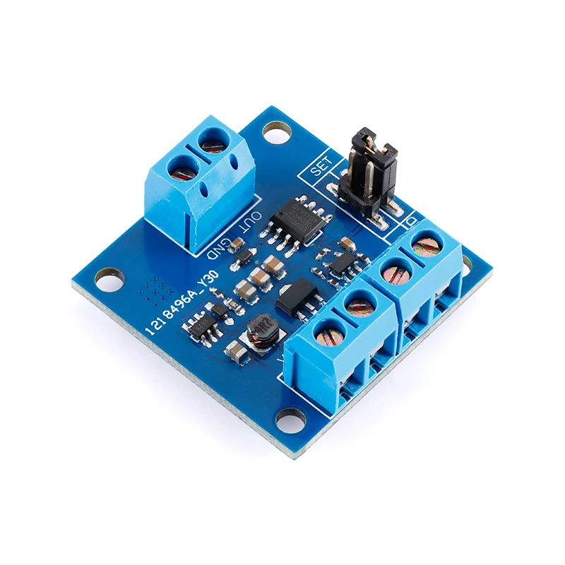
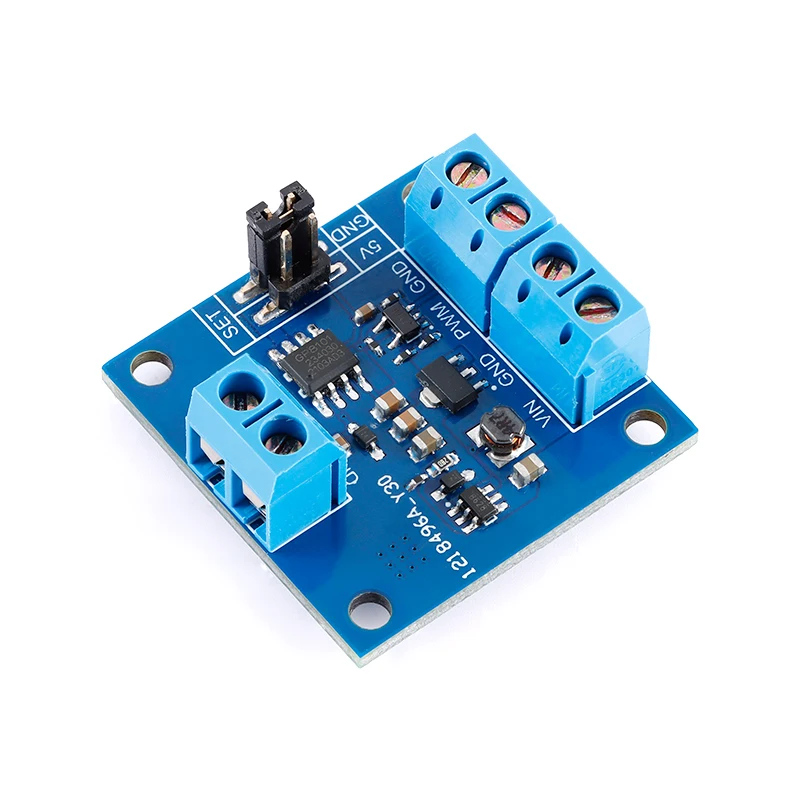
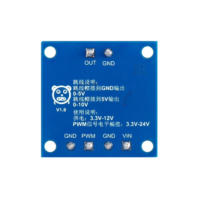
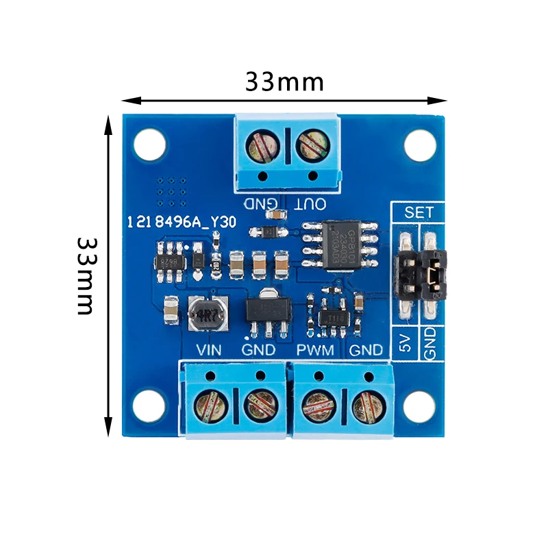
The PWM to voltage module can convert 0% – 100% duty cycle PWM into 0V-5V or 0V-10V voltage output.The module can change the range of output voltage by selecting the position of jumper cap. The jumper cap is inserted at the GND end, that is, the SET and GND are shorted, and the output range is 0V-5V; When the jumper cap is inserted into the 5V
end, the SET and 5V are shorted, and the output range is 0V-10V.
This module can cooperate with the motor/LED and other drive boards that can becontrolled by analog signals to quickly realize motor speed regulation/light brightness
adjustment and other functions.
Parameters:
Working voltage: 3.3V – 12V
Working current: 9.5 – 21.5mA (no-load test, actual use may be slightly higher thanthe test value)
Input signal level:+3.3V -+24V (PWM high level is+3 .3V -+24V, low level is 0V)
Input signal frequency: 22Hz- 20kHz
Output level: 0V – 5V/0V-10V
i2 M Press,0.Com
Allowable output error:土1.2% (22Hz – 20kHz)
With or without isolation: No
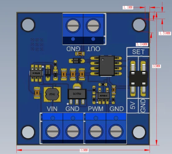
Module size: 33mm * 33mm
Positioning mode: M3 screw
Pin description:
VIN: positive pole of module power supply, power supply range 3.3V- 12V
GND: module power supply, signal, output cathode
PWM: PWM input, frequency 22Hz – 20kHz amplitude+3.3V -+24V
OUT: output voltage positive pole, output0V – 5V or0V- 10V
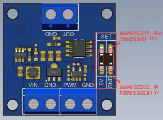
The jumper cap must not be inserted at 5V and GND.
Note:
The power supply of the module is strictly controlled within 12V. When the input PWM frequency is less than 22Hz and the duty cycle is less than 10%, the output may have problems. Therefore, when using, please ensure that the input PWM frequency is greater than 22Hz or the duty cycle is greater than 10%.
The higher the input PWM frequency of the module is, the greater the output voltage error is compared with the low frequency, and the allowable error of the product parameters shall be followed when using within the allowable parameters. The output accuracy of the tested input PWM frequency is high under the condition of 2kHz – 8kHz
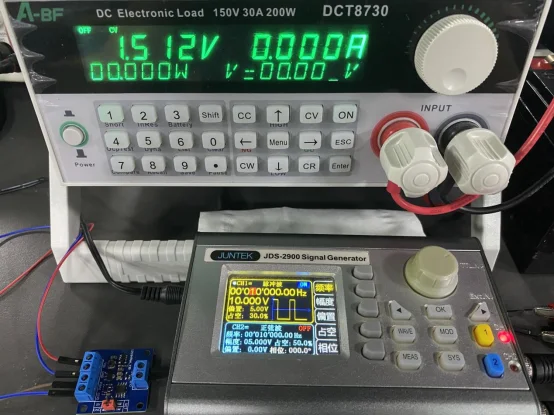
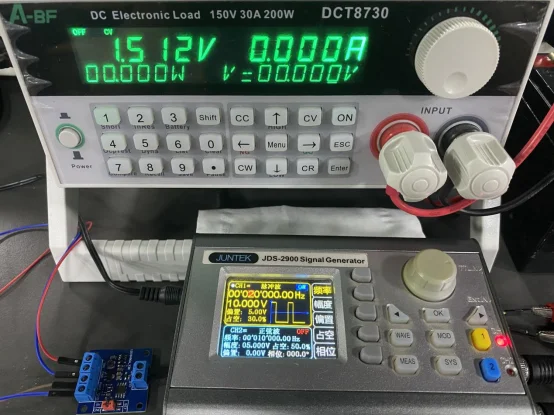
0V – 10V gear, input 70% duty cycle to test the duty cycle of 20K, 10K and 1K frequency respectively
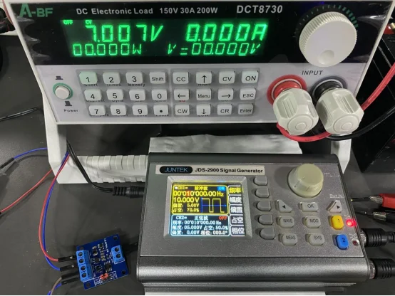
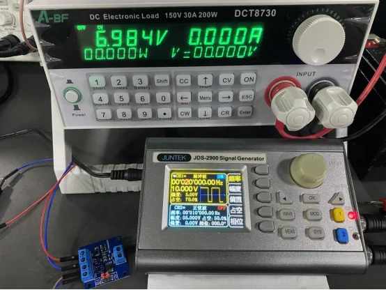
0V – 10V gear, input 20% duty cycle to test the duty cycle of 20K, 10K and 1K frequency respectively
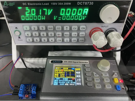
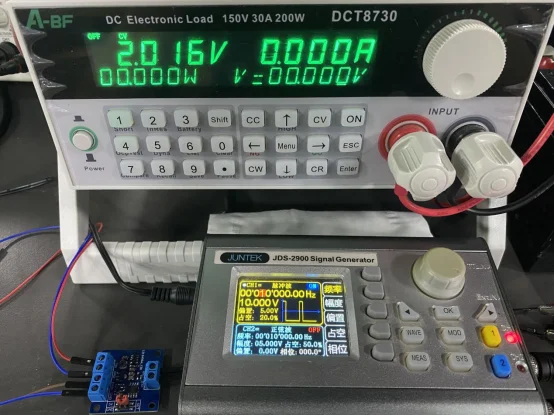
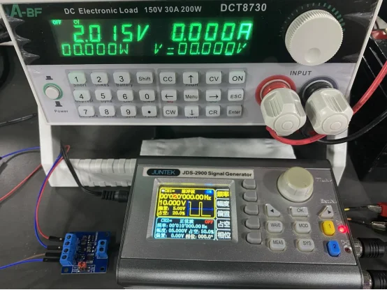
0V – 5V gear, input 90% duty cycle to test the duty cycle of 20K, 10K and 1K frequency respectively
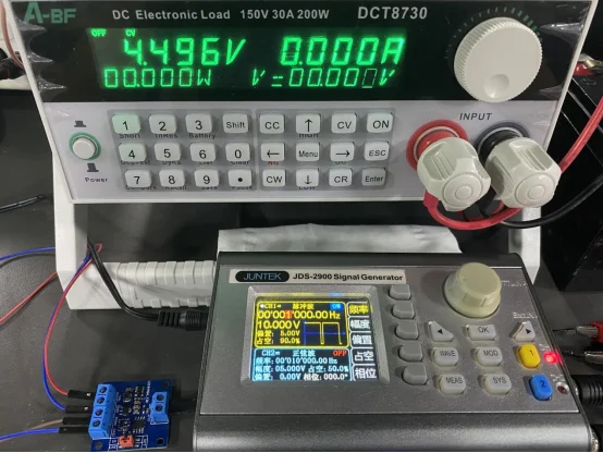
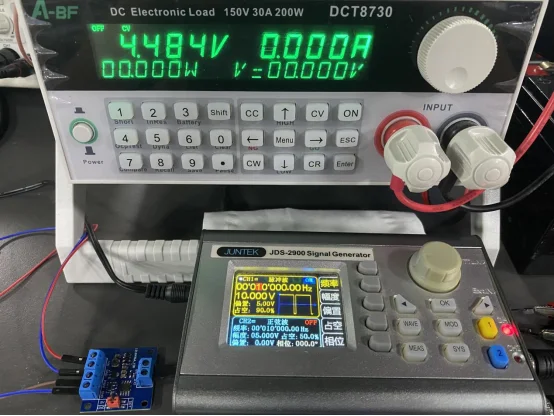
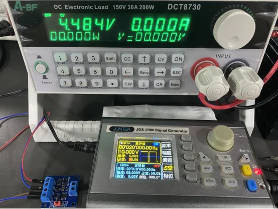
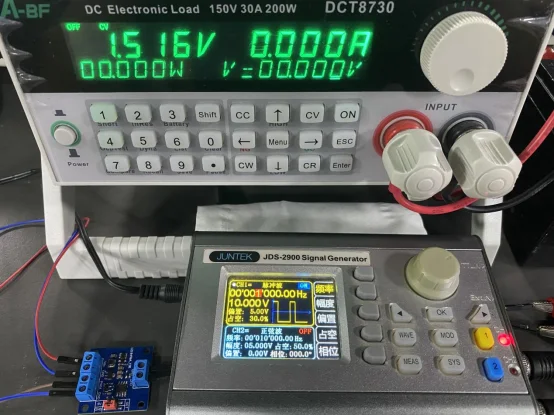
0V – 5V gear, input 30% duty cycle to test the duty cycle of 20K, 10K and 1K frequency respectively













Recensioni
Ancora non ci sono recensioni.