
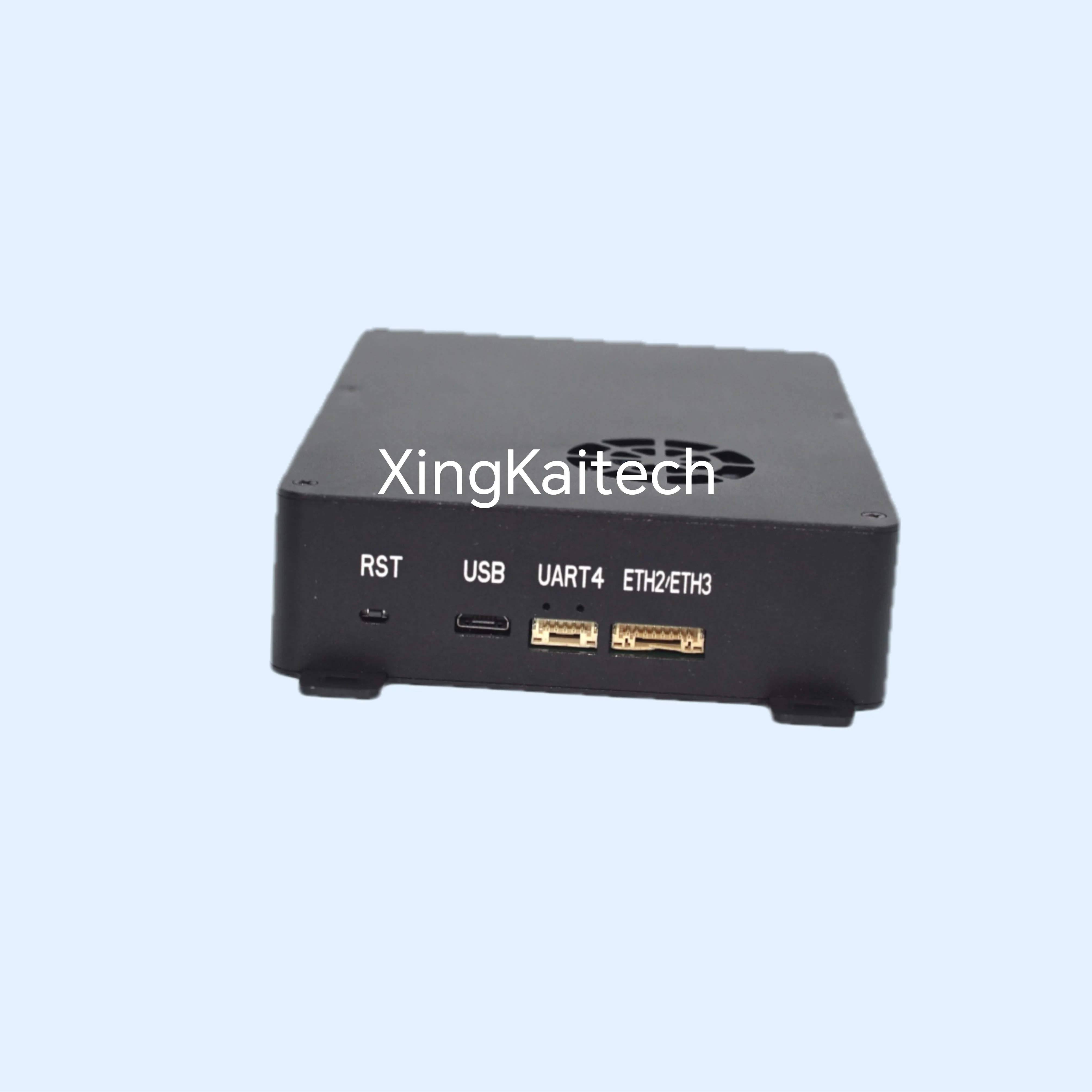
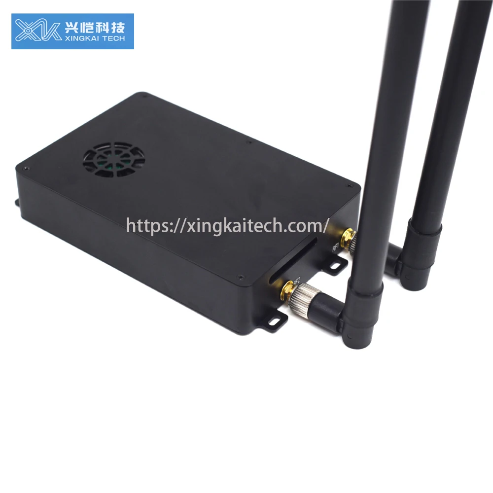
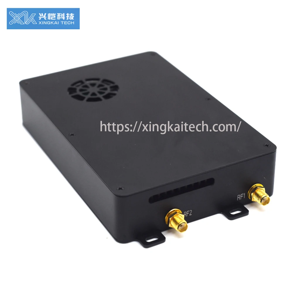
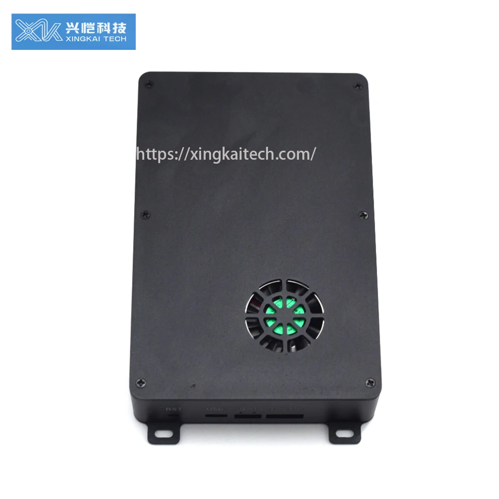
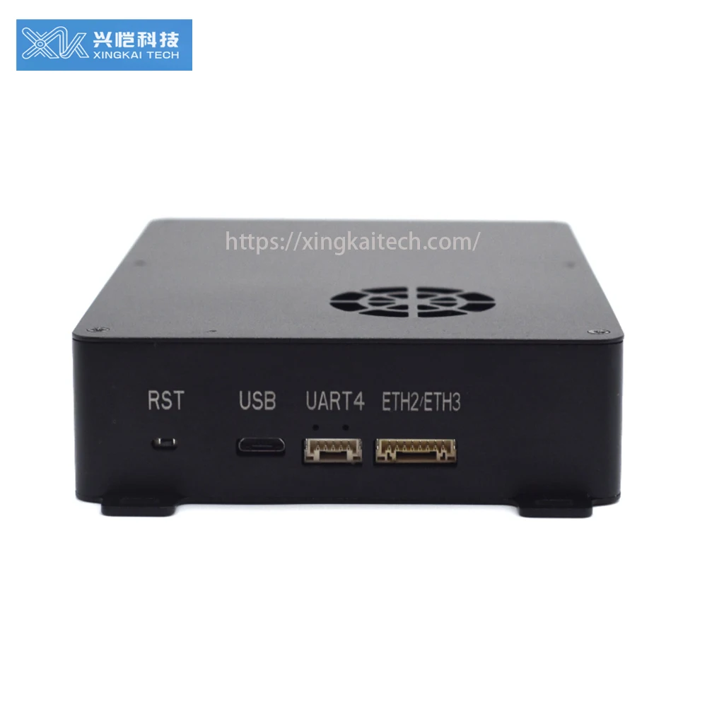
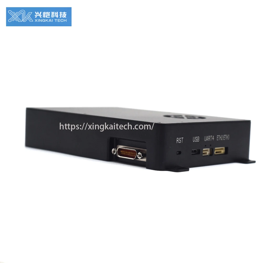
VTOL Drone IP Mesh Network Transmission IP Encoder Long Range Airborne Transmission Module Integrated Definition Transmitter
|
Product Name
|
XK-M413E
|
|
Function
|
MIMO MESH RADIO for Surveillance
|
|
Package
|
Packed in a professional shipping box
|
1. Product Overview
XK-M413 mesh radio is themobile broadband multimedia communication system based on based on LTE wireless communication standard. The mesh network adopts the same frequency networking and multi-hop relay. Each node can move quickly and randomly, and the network topology can be changed and updated quickly without affecting the network transmission. The whole network is convenient to deploy, flexible to use, simple to operate and easy to maintain. It can provide users with reliable, timely, efficient and secure full IP broadband data, high-definition video and visual command and scheduling and other multimedia integrated services under complex application scenarios such as fast movement and non-line-of-sight shielding.
The broadband self-organizing network can be widely used in the military,public security, armed police, fire protection, civil air defense, electric power, petroleum, mining, transportation, water conservancy, forestry, radio and television, medical, water and air communications and other sectors, providing users with reliable, timely, Rich integrated services such as safe and efficient voice, data, video and visual command and dispatch can meet users’wireless broadband communication needs in normal or emergency situations to the greatest extent, and truly achieve “anytime, anywhere on demand”.
Significant applications in Non Line of Sight /Multi path Fading environments, video/data/critical communications:
* Robot/Unmanned
* Vehicle,Reconnaissance/Surveillance/Anti-Terrorism/Monitoring
* Air-to-air&air-to-ground&ground-to-ground,public safety/special operations
* Urban network,emergency support/normal patrol/traffic management
* Inside and outside the building,firefighting/rescue and disaster relief/forest/civil air defense/earthquake
* TV broadcast wireless audio/video/live broadcast
* Marine communication/high speed transmission on the opposite side of the ship
* Low deck wireless network/ship landing
* Mine/tunnel/basement connection
2. Product features and functions
2.1 Product features
* Self-assembling network with no centre homodyne frequency.
* Point-to-point, point-to-multipoint, trunking, mesh networking, etc.
* Fast multi-node networking.
* High carrier-to-noise ratio.
* Wide input voltage range, supports DC12~28V voltage input.
* Low power consumption.
* Support OTA upgrade, support local and remote upgrade.
* Supports AES source encryption.
2.2 Product functions
u The operating frequency band can be optionally 600MHz/1.4GHz.
u Adjustable bandwidth among 3MHz, 5MHz, 10MHz and 20MHz.
u Supporting three serial ports and one SBUS.
u Supporting simultaneous transmission of at most 3 network ports.
3. Technical Parameters
|
Item |
Spec/Parameters |
|
Operation Voltage |
DC 12V~DC28V,Standard input DC16.8V |
|
Power Consumption |
≤20W @ 33dBm |
|
Modulation |
Supports QPSK, 16QAM, 64QAM modulations |
|
Data interface |
UART(TTL/RS232/RS485)/SBUS |
|
Frequency |
1420-1530MHz |
|
Channel rate |
bandwidth :20MHz, Transmission not less than 100Mbps |
|
Bandwidth |
3/5/10/20MHz |
|
Latency |
≤15ms |
|
Tx Power |
2*33dBm(Adjustable) |
|
single-hop delay |
≤20ms |
|
Maximum number of networks |
32 |
|
Maximum supported hops |
31 |
|
transmission distance |
100KM(inter-nodal) |
|
encryption method |
AES128 |
|
Working temperature |
-30℃~60℃ |
|
Storage temperature |
-40℃~75℃ |
|
Communication Protocol |
IEEE802.3,Transparent serial data |
|
Communication |
Distributed centreless point-to-point, point-to-multipoint, relay mode, mesh networking |
|
Dimensions |
135*90*27.5mm |
|
Weight |
≤350g |
4. Installation instructions
4.1 Installation Diagram

Fig. 4.1 Schematic diagram of air device installation and connection
4.2 Installation Instructions
The XK-M413 two-way graphic-digital integrated device is shown in Figure 5.1. The specific installation steps are as follows:
① Connect the main and secondary antennas of the corresponding frequency points to Port RF1 and RF2 first, andmake sure that the connection is tight;
②The network port is directly connected to the relevant device (PC/camera, etc.);
③SBUS interface, mainly for telemetry data;
④ If the user’s serial datais needed to be transmitted, use a USB serial cable to connect it to the PC;
⑤ Finally, power on.















Recensioni
Ancora non ci sono recensioni.